Modem is abbreviation for Modulator – Demodulator. Modems are used for data transfer from one computer network to another computer network through telephone lines. The computer network works in digital mode, while analog technology is used for carrying massages across phone lines.

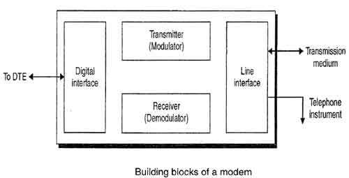
Modulator converts information from digital mode to analog mode at the transmitting end anddemodulator converts the same from analog to digital at receiving end. The process of converting analog signals of one computer network into digital signals of another computer network so they can be processed by a receiving computer is referred to as digitizing.
When an analog facility is used for data communication between two digital devices called Data Terminal Equipment (DTE), modems are used at each end. DTE can be a terminal or a computer.
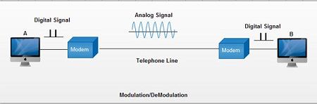
The modem at the transmitting end converts the digital signal generated by DTE into an analog signal by modulating a carrier. This modem at the receiving end demodulates the carrier and hand over the demodulated digital signal to the DTE.
The transmission medium between the two modems can be dedicated circuit or a switched telephone circuit. If a switched telephone circuit is used, then the modems are connected to the local telephone exchanges. Whenever data transmission is required connection between the modems is established through telephone exchanges.
Ready to Send
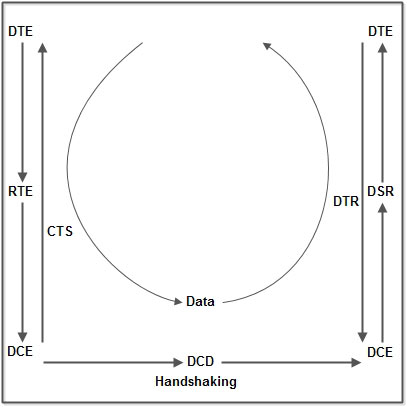
To begin with the Data Terminal Equipment or DTE (better known as a computer) sends a Ready To Send or RTS signal to the Data Communication Equipment or DCE (better known as a modem). This is sometimes known as a wakeup call and results in the modem sending a Data Carrier Detect or DCD signal to the receiving modem. There then follows a series of signals passed between the two until the communication channel has been established. This process is known as handshaking and helps to explain why, even now, some companies like CompuServe use the symbol of two hands grasping each other to mean being on-line. Of course, after that all it takes is for the second modem to send a Data Set Ready or DSR signal to its computer and wait for the Data Terminal Ready or DTR reply. When that happens the first modem sends a Clear To Send or CTS signal to the computer that started the whole process off and data can then be transmitted. It is as simple as that.
Alternatively, for anyone confused by what the entire Internet industry dubs TLA's which means Three Letter Acronyms, the following diagram should help.
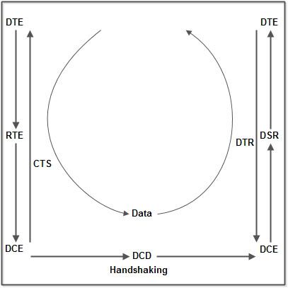
It only looks confusing. Take a second look and everything will soon become obvious.
By way of completeness, these signals are all sent through different pins in the plug which is why the handbooks for all modems and printers carry a pin diagram somewhere in the section on troubleshooting. They are also standardized after the industry leaders met to agree standards for a whole range of peripheral equipment. The Recommended Standard for cable was number 232 which explains that one technical term probably everybody has heard of: RS 232.
Of course, that still leaves the question of exactly how data is transferred from one computer to another; something that is more of a problem than might first appear mainly because the phone lines are analogue while computers are digital. In simple terms this means a telephone signal is constantly changing. To understand that just think of a sine wave as produced on an oscilloscope. The signal might be constant, but it is constantly changing from positive to negative and back again in a series of smooth curves. Computers, on the other hand, can only understand information when it is presented as a string of binary digits so the idea is to map digital output onto an analogue signal.
Without going into technical details this is done by superimposing different frequencies onto the analogue signal (which then becomes known as the carrier wave). Different frequencies can then represent different groups of binary digits in a process which is known as modulation when it is being transmitted and demodulation when it is decoded at the receiving end. Naturally two way communication is achieved by having a single device being capable of both modulation and demodulation, from which the unit takes its name: the modem.
From this it becomes obvious that the more frequencies that can be superimposed on the carrier wave the faster data can be transmitted. Alternatively, to take a different point of view, the more data there is to be transmitted so the more frequencies are needed.
Unfortunately it is only possible to send a limited number of frequencies at the same time, known as the bandwidth, which means communication takes that much longer as the size of the signals steadily increases. Now that pictures, sound and even video sequences are transmitted over the Internet on a regular basis, and as these all call for massive data files, the amount of available bandwidth is likely to be a problem for some time.
Finally, as the whole process comes down to sending binary digits or bits over a phone line the speed of the system is expressed as Bits Per Second or BPS which is a figure quoted by all the modem manufacturers.
Unfortunately when it comes to data communications there is a lot more involved than just how fast bits can be sent down a phone line. There is also the problem of what those bits mean and how they can be assembled into something intelligible at the far end. Here a whole range of issues need to be addressed and so it might be a good idea to briefly look at the first of these which are the transmission protocols.
Types of Modems
• Modems can be of several types and they can be categorized in a number of ways.
• Categorization is usually based on the following basic modem features:
1. Directional capacity: half duplex modem and full duplex modem.
2. Connection to the line: 2-wire modem and 4-wire modem.
3. Transmission mode: asynchronous modem and synchronous modem.
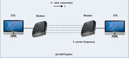
Half duplex and full duplex Modems
Half duplex
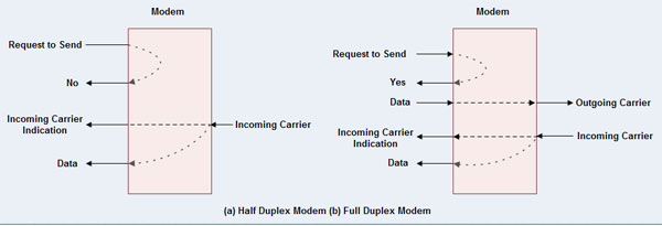
1. A half duplex modem permits transmission in one direction at a time.
2. If a carrier is detected on the line by the modem, I gives an indication of the incoming carrier to the DTE through a control signal of its digital interface.
3. As long as they camel' IS being received; the modem does not give permission to the DTE to transmit data.
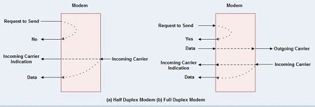
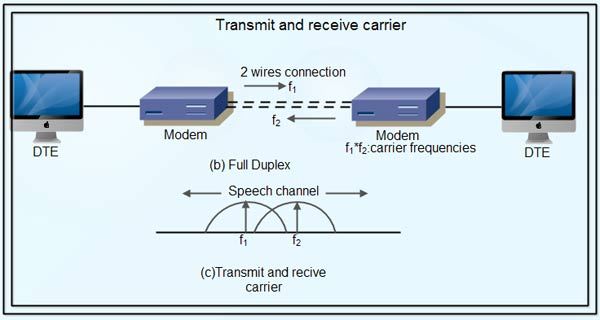
Full duplex
• A full duplex modem allows simultaneous transmission in both directions.
• Therefore, there are two carriers on the line, one outgoing and the other incoming. Wire and 4-wire Modems
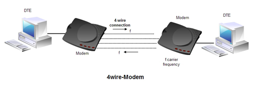
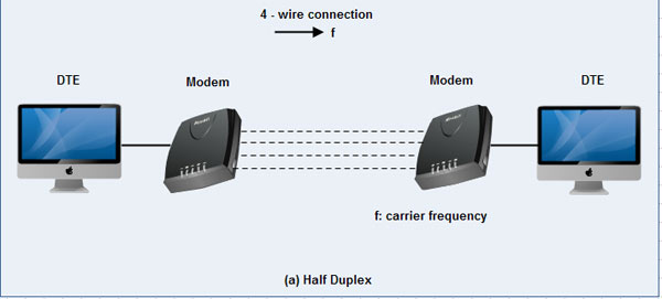
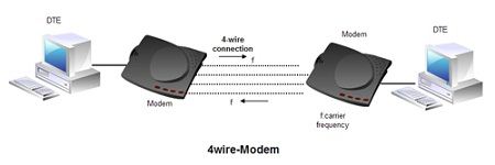
• The line interface of the modem can have a 2-wire or a 4-wire connection to transmission medium. 4-wire Modem
• In a 4-wire connection, one pair of wires is used for the outgoing carrier and the other pair is used for incoming carrier.
• Full duplex and half duplex modes of data transmission are possible on a 4- wire connection.
• As the physical transmission path for each direction is separate, the same carrier frequency can be used for both the directions.
2-wire Modem
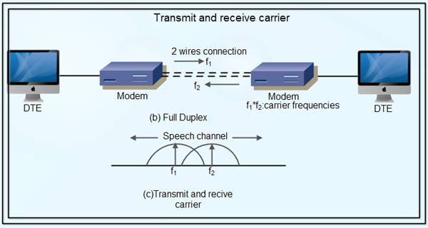
• 2-wire modems use the same pair of wires for outgoing and incoming carriers.
• A leased 2-wireconrlection is usually cheaper than a 4-wire connection as only one pair of wires is extended to the subscriber's premises.
• The data connection established through telephone exchange is also a 2-wire connection.
• In 2-wire modems, half duplex mode of transmission that uses the same frequency for the incoming and outgoing carriers can be easily implemented.
• For full duplex mode of operation, it is necessary to have two transmission channels, one for transmit direction and the other for receive direction.
• This is achieved by frequency division multiplexing of two different carrier frequencies. These carriers are placed within the bandwidth of the speech channel.
Asynchronous & Synchronous Modems
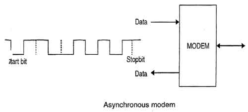
Asynchronous Modem
• Asynchronous modems can handle data bytes with start and stop bits.
• There is no separate timing signal or clock between the modem and the DTE.
• The internal timing pulses are synchronized repeatedly to the leading edge of the start pulse .

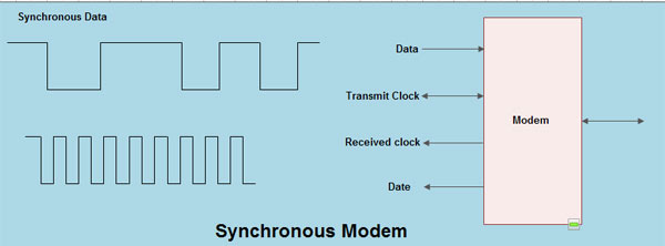
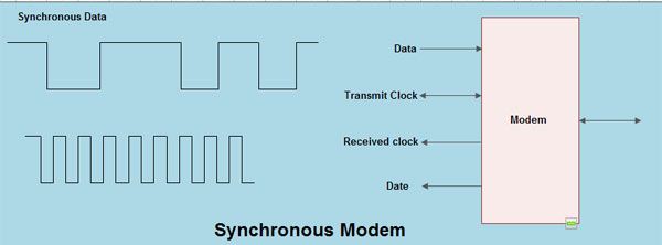
Synchronous Modem
• Synchronous modems can handle a continuous stream of data bits but requires a clock signal.
• The data bits are always synchronized to the clock signal.
• There are separate clocks for the data bits being transmitted and received.
• For synchronous transmission of data bits, the DTE can use its internal clock and supply the same to the modem.
Modulation techniques used for Modem:
The basic modulation techniques used by a modem to convert digital data to analog signals are :
• Amplitude shift keying (ASK).
• Frequency shift keying (FSK).
• Phase shift keying (PSK).
• Differential PSK (DPSK).
These techniques are known as the binary continuous wave (CW) modulation.
• Modems are always used in pairs. Any system whether simplex, half duplex or full duplex requires a modem at the transmitting as well as the receiving end.
• Thus a modem acts as the electronic bridge between two worlds - the world of purely digital signals and the established analog world.
Is this make using AI?
ReplyDelete