Virtual Private Networks creates a tunnel for using a public network (such as Internet) to transfer information between client's PC and office's network. To initiate tunnel in client PC it must have VPN software to connect the ISP router (RAS). After verification of validity of user, software establishes the connection between ISP and use client machine.
The data packets sent through tunnel are encapsulated by the tunneling protocol in an additional header. The additional header provides routing information so that the encapsulated payload can traverse the intermediate inter-network (Public network, i.e. Internet). When the packets arrive at destination, the VPN software strips the header off the packets (or unencapsulates the packets) and send it to its destination on the local network.
The data packets sent through tunnel are encapsulated by the tunneling protocol in an additional header. The additional header provides routing information so that the encapsulated payload can traverse the intermediate inter-network (Public network, i.e. Internet). When the packets arrive at destination, the VPN software strips the header off the packets (or unencapsulates the packets) and send it to its destination on the local network.
Tunneling comprises the entire process of encapsulation, transmission, and extraction of packets.
Examples of Matured Tunneling Technologies
There are some tunneling technologies that are established and have been in existence for sometime. Some examples of mature technologies include:
(i) SNA 'funneling over IP Inter-networks. When System Network Architecture (SNA) traffic is sent across a corporate IP inter-network, the SNA frame is encapsulated in a UDP and IP header.
(ii) IPX tunneling for Novell NetWare over IP inter-networks. When an IPX packet is sent to a NetWare server or IPX router, the server or the router wraps the IPX packet in a UDP and IP header, and then sends it across an IP inter-network. The destination IP-to-IPX router removes the UDP and IP header and forwards the packet to the IPX destination.
(Hi)Point-to-Point Tunneling Protocol (PPTP) allows IP, IPX, or NetBEUI traffic to be encrypted, and then encapsulated in an IP header to be sent across a corporate IP inter-network or a public IP inter-network such as the Internet.
(iv)Layer 2 'funneling Protocol (L2TP). L2TP allows IP, IPX, or NetBEUI traffic to be encrypted, and then sent over any medium that supports point-to-point datagram delivery, such as IP, X.25, Frame Relay, or ATM.
(v) IP Security (IPSec) Tunnel Mode. IPSec Tunnel Mode allows IP payloads to be encrypted, and then encapsulated in an IP header to be sent across a corporate IP inter-network or a public IP inter-network such as the Internet.
Tunneling Technologies
Tunneling technology can be based on either a Layer 2 or a Layer 3 Tunneling protocol. These layers correspond to the 7 layers OSI Reference Model.
Layer 2 tunneling technologies: A tunnel is similar to a session; both of the tunnel endpoints must agree to the tunnel and must negotiate configuration variables, such as address assignment or encryption or compression parameters. In most cases, data transferred across the tunnel is sent using a datagram-based protocol. A tunnel maintenance protocol is used as the mechanism to manage the tunnel.
Layer 3 tunneling technologies: These tunneling technologies generally assume that all of the configuration issues have been handled out of band, often by manual processes. For these protocols, there may be no tunnel maintenance phase. For Layer 2 protocols (PPTP and L2TP), however, a tunnel must be created, maintained, and then terminated.
Once the tunnel is established, tunneled data can be sent. The tunnel client or server uses a tunnel data transfer protocol to prepare the data for transfer. For example, when the tunnel client sends a data to the tunnel server, the tunnel client first adds a tunnel data transfer protocol header to the payload. The client then sends the resulting encapsulated data or packets across the Internet, which routes it to the tunnel server. The tunnel server accepts the packets, removes the tunnel data transfer protocol header, and forwards the payload to the target network.
Tunneling Protocols
As with other communication technologies tunneling is also standardized by means of tunneling protocols. To establish a tunnel, both the tunnel client and the tunnel server must have the same tunneling protocol.
Layer 2 Tunneling Protocols
Layer 2 protocols correspond to the data-link layer and use frames as their unit of exchange. PPTP and L2TP and Layer 2 Forwarding (L2F) are Layer 2 tunneling protocols; both encapsulate the data in a PPP frame to be sent across an Internet.
Point-to-Point Tunneling Protocol (PPTP)
Point-to-Point Tunneling Protocol is a new technology for creating Virtual Private Networks (VPN) developed by a forum. PPTP is a Layer 2 protocol that encapsulates PPP frames in IP datagrams for transmission over an IP inter-network, such as the Internet PPTP can also be used in private LAN-to-LAN networking.
PPTP uses a TCP connection for tunnel maintenance and GRE (generic routing encapsulation) encapsulated PPP frames for tunneled data. The payloads of the encapsulated PPP frames can be encrypted and /or compressed. PPTP supports multiple network protocols (IP, IPX, and NetBEUI) and can be used or virtual private networking over public and private networks.
PPTP can be used to provide secure, on-demand, virtual networks by using dial-up lines, LANs,
WANs, the Internet, and other public TCP/IP-based networks. PPTP uses the VPN device to establish and maintain private, secure communication between computers.
The secure communication created using the PPTP protocol involves three processes, each of which requires successful completion of the previous process.
(i) PPP Connection and Communication: PPP is used by the PYI'P client to establish connection to an ISP and encrypt data packets to travel through a telephone line or ISDN line.
(ii) PPTP Control Connection: After connecting to the Internet using the PPP protocol, the PPTP protocol establishes a control connection from the PYI'P client to a PYI'P server. This connection uses TCP to establish the connection called a PYI'P tunnel.
(iii) PPTP Data 'funneling: IP datagrams are then created by the PPTP protocol. These datagrams contain encrypted PPP packets which are then sent to the PPTP server through the PPTP tunnel. The PPTP server decrypts the PPP packets, and then routes the decrypted packets to the private network
Security-Features Available in Point-to-Point Tunneling
Authentication is one of the features in PPPT; it uses the security provided through PPP authentication method. PPTY also can protect the PPTP server and private network by ignoring all but PPTP traffic. Despite the strict security, it is very simple to use PPTP with existing firewalls.
The data encryption is another security feature in PPTP; encrypted data is sent through the PPTP tunnel. Data is invisible to the outside since the network traffic in a PPTP flows inside the tunnel.
A2. Layer 2 Forwarding (L2F)
L2F, a technology proposed by Cisco, is a transmission protocol that allows dial-up access servers to frame 'dial-up traffic in PPP and transmit it over WAN links to an L2F server (a router). The L2F server then unwraps the packets and injects them into the network. Unlike PPTP and L2TP, L2F has no defined client. L2F functions in compulsory tunnels only.
A3. Layer 2 Tunneling Protocol (L2TP)
L2TP is a combination of PPTP and L2F. Its designers hope that L2TPwill represent the best features of PPTP and L2F.
L2TP is a network protocol that encapsulates PPP frames to be sent over IP, X.25, Frame Relay, or Asynchronous Transfer Mode (ATM) networks. When configured to use IP as its datagram transport, L2TP can be used as a tunneling protocol over the Internet. L2TP can also be used directly over various WAN media (such as Frame Relay) without an IPtransport layer.
L2TP over IP inter-networks uses UDP and a series of L2TP messages for tunnel maintenance. L2TP also uses UDP to send L2T .P-encapsulated PPP frames as the tunneled data. The payloads of encapsulated PPP frames can be encrypted and/or compressed. How an L2TP packet is assembled prior to transmission. The drawing shows a dial-up client creating a tunnel across an inter-network. The final frame layout shows the encapsulation for a dial-up client (PPP Device Driver). The encapsulation assumes L2TP over IP.
L2TP can help reduce the cost of remote dial-up networking for users who normally dial into a corporate network over a long distance connection. L2TP is often called a "virtual dial-up protocol" because it extends a dial ·up PPP session across the Internet. Consider the traditional dial-up session without tunneling: a remote user in Los Angeles who needs to connect with the corporate network in New York dials the home office remote access telephone number. A dedicated circuit is created across the PSTN (from 'LA. to New York. Obviously, this is not a cost-effective way to access the corporate network. In addition, the long-distance call does not meet the digital requirements for V.90 modems, so the data rate is usually around 33 Kbits/sec or worse, not the 56 Kbits/sec that is possible with V.90 modems.
Key L2TP Terms
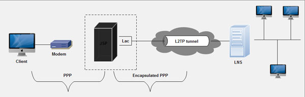
L2TP Access Concentrator (LAC): An LAC device is attached to the switched network fabric, such as Public Switched Telephone Network (PSTN) or ISDN or collocated with a PPP end system capable of handling the L2TP protocol. An LAC only needs to implement the media, over which L2TP operates in order to pass traffic to one or more LNSs. It may tunnel any protocol carried within PPP. LAC is the initiator of incoming calls and the receiver of outgoing calls. It is also known as the network access server in Layer 2 Forwarding (L2F).
L2TP Network Server (LNS): LNS operates on any platform capable of PPP termination. LNS handle the server side of the L2TP protocol. Since L2TP relies only on the single media over which L2TP tunnels arrive, LNS may only have a single LAN or WAN interlace, yet still be able to terminate calls arriving at any LACs full range of PPP interfaces (async, ISDN, PPP over ATM, PPP over Frame Relay). It is the initiator of outgoing calls and the receiver of incoming calls. LNS is also known as Home Gateway (HGW) in L2F terminology.
Network Access Server: This device provides temporary, on-demand network access to users. This access is point-to-point, typically using PSTN or ISDN lines. In the Cisco implementation, an NAS serves as an LAC.
L2TP Illustration
With L2TP, the remote user connects to the Internet via a local ISP or by using one of the national ISPs that have local dial-up numbers throughout the country. As shown in the following illustration, native PPP runs over the dial-up link between the user and the CO. An L2TP access concentrator (LAC) then virtually extends PPP across the Internet to an L2TP network server (LNS), which is located at the corporate network. This is where the PPP session officially terminates.

1. The client dials the ISP using an analog phone or ISDN. In this case, the client's computer is configured with PPP, although a client may also run L2TP directly.
2. When the call arrives at the ISP's LAC, the LAC performs a call check by contacting a RADIUS server. The RADIUS server responds with accept or reject message. If accepted, the reply will also specify that an L2TP tunnel is needed.
3. The LAC creates a tunnel to the LNS at the client's corporate site. This is done by sending a message to UDP port 1701.An authentication procedure takes place between the LAC and the LNS.
4. A tunnel is set up and the client begins communicating with the corporate LCP using PPP. The client first sends PPP authentication information to the LCP, which in turn authenticates the client.
The client's PPP frames are encapsulated into IP packets with an L2TP tunneling header and sent across the Internet connection. The LCP strips off the L2TP header to access the PPP frames. Note that the LAC does not authenticate the client during the set-up phase, but it does check with RADIUS to make sure that the dial-up session is allowed. The client is authenticated by the corporate server, just as if he or she logged on from a node directly attached to that network.
Implementation of L2TP
Cisco has implemented L2TP into its IOS software, and offers a standard way to provide Access Virtual Private Networks (VPNs),
A key building block for Access VPNs is L2TP (Layer 2 Tunneling Protocol), an extension to the
Point-to-Point Protocol (PPP) and a fundamental building block for VPNs. L2TP merge the best features of two other tunneling protocols: Layer 2 Forwarding (L2F) from Cisco Systems and Point-to-Point Tunneling (PPTP) from Microsoft. L2TP is an Internet Engineering Task Force (IETF) emerging standard, currently under co-development and endorsed by Cisco Systems, Microsoft, Ascend, 3Com, and other networking industry leaders.
PPTP Compared to L2TP
Both PPTP and L2TP use PPP to provide an initial envelope for the data, and then append additional headers for transport through the inter-network. The two protocols are very similar. However, there are differences between PPTP and L2TP:
- PPTP requires that the inter-network be an IP inter-network. L2TP requires only that the tunnel media provide packet-oriented point-to-point connectivity. L2TP can be used over IP (using UDP), Frame Relay permanent virtual circuits (PVCs), X.25 virtual circuits (VCs), or ATM VCs.
- PPTP can support only a single tunnel between end points. L2TP allows for the use of multiple tunnels between end points. With L2TP, you can create different tunnels for different qualities of service.
- L2TP provides for header compression. When header compression is enabled, L2TP operates with 4 bytes of overhead, as compared to 6 bytes for PPTP.
- L2TP provides for tunnel authentication, while PPTP does not. However, when either protocol is used over IPSec, tunnel authentication is provided by IPSec so that Layer 2 tunnel authentication is not necessary,
Layer 3 Tunneling Protocols
Layer 3 protocols correspond to the Network layer, and use packets. IP-over-IP and IPSec Tunnel Mode are examples of Layer 3 tunneling protocols. These protocols encapsulate IP packets in an additional IP header before sending them across an IP Internet.
B1. IPSec Tunnel Mode
IPSec is a Layer 3 protocol standard that supports the secured transfer of information across an IP inter-network. IPSec is more fully described in the Advanced Security section below. In addition to its definition of encryption mechanisms for IP traffic, IPSec defines the packet format for an IP over IP tunnel mode, generally referred to as IPSec Tunnel Mode. An IPSec tunnel consists of a tunnel client and a tunnel server, which are both configured to use IPSec tunneling and a negotiated encryption mechanism.
IPSec Tunnel Mode uses the negotiated security method (if any) to encapsulate and encrypt entire IP packets for secure transfer across a private or public IP inter-network. The encrypted payload is then encapsulated again with a plain-text IP header and sent on the inter-network for delivery to the tunnel server. Upon receipt of this datagram, the tunnel server processes and discards the plain-text IP header, and then decrypts its contents to retrieve the original payload IP packet. The payload IP packet is then processed normally and routed to its destination on the target network.
IPSec Tunnel Mode has the following features and limitations:
- It supports IP traffic only
- It functions at the bottom of the IP stack! therefore, applications and higher-level protocols inherit its behavior
- It is controlled by a security policy - a set of filter-matching rules. This security policy establishes the encryption and tunneling mechanisms available, in order of preference, and the authentication methods available, also in order of preference. As soon as there is traffic, the two computers perform mutual authentication, and then negotiate the encryption methods to be used. Thereafter, all traffic is encrypted using the negotiated encryption mechanism, and then wrapped in a tunnel header.
Tunneling Protocols and the Basic Tunneling Requirements
Tunneling protocols are based on the well-defined PPP protocol, so Layer 2 protocols (such as PPTP and L2TP) inherit a suite of useful features from it. These features and their Layer 3 counterparts address the basic VPN requirements, as outlined below.
- User Authentication Layer 2 tunneling protocols inherit the user authentication schemes of
- PPP, including the EAP methods discussed below. Many Layer 3 tunneling schemes assume that the endpoints were well-known (and authenticated) before the tunnel was established. An exception to this is IPSec ISAKMP negotiation, which provides mutual authentication of the tunnel endpoints. (Most IPSec implementations support computer-based certificates only, rather than user certificates. As a result, any user with access to one of the endpoint computers can use the tunnel. This potential security weakness can be eliminated when IPSec is paired with a Layer 2 protocol such as L2TP.)
- Token card support Using the Extensible Authentication Protocol (EAP, Layer 2 tunneling protocols can support a wide variety of authentication methods, including one-time passwords, cryptographic calculators, and smart cards. Layer 3 tunneling protocols can use similar methods; for example, IPSec defines public key certificate authentication in its ISAKMP/Oakley negotiation.
- Dynamic address assignment Layer 2 tunneling supports dynamic assignment of clientaddresses based on the Network Control Protocol (NCP) negotiation mechanism. Generally,
- Layer 3 tunneling schemes assume that an address has already been assigned prior to initiation of the tunnel. Schemes (or assignment of addresses in IPSec tunnel modes are currently under development and are not yet available.
- Data compression Layer 2 tunneling protocols support PPP-based compression schemes. For example, the Microsoft implementations of both PPTP andL2TP use Microsoft Point-to-Point Compression (MPPC). The IETF is investigating similar mechanisms (such as IP Compression) for the Layer 3 tunneling protocols.
- Data encryption Layer 2 tunneling protocols support PPP-based data encryption mechanisms. The Microsoft implementation of PPTP supports optional use of Microsoft Point-to-Point Encryption (MPPE), based on the RSAlRC4 algorithm. Layer 3 tunneling protocols can use similar methods; for example, IPSec defines several optional data encryption methods, which are negotiated during the ISAKMP/Oakley exchange. The Microsoft implementation of the L2TP protocol uses IPSec encryption to -protect the data stream from the client to the tunnel server.
- Key management MPPE, a Layer 2 protocol, relies on the initial key generated during user authentication, and then refreshes it periodically. IPSec explicitly negotiates a common key during the ISAKMP exchange, and also refreshes it periodically.
- Multiprotocol support Layer 2 tunneling supports multiple payload protocols, which makes it easy for tunneling clients to access their corporate networks using IP, IPX, NetB1;.UI,and so on. In contrast, Layer 3 tunneling protocols, such as IPSec tunnel mode, typically support only target networks that use the IP protocol.
Tunnel Types
Tunnels can be created in various ways:
- Voluntary tunnels: A user or client computer can issue a VPN request to configure and create a voluntary tunnel. In this case, the user's computer is a tunnel endpoint and acts as the tunnel client.
- Compulsory tunnels: AVPN-capable dial-up access server configures and creates a compulsory tunnel. With a compulsory tunnel, the user's computer is not a tunnel endpoint. Another device, the remote access server, between the user's computer and the tunnel server is the tunnel endpoint and acts as the tunnel client.
To date, voluntary tunnels are proving to be the more popular type of tunnel. The following sections describe each of these tunnel types in greater detail.
- Voluntary Tunneling
Voluntary tunneling occurs when a workstation or routing server uses tunneling client software to 'create a virtual connection to the target tunnel server. To accomplish this, the appropriate tunneling protocol must be installed on the client computer. For the protocols discussed in this paper, voluntary tunnels require an IP connection (either LAN or dial-up).
In a dial-up situation, the client must establish a dial-up connection to the inter-network before the client can set up a tunnel. This is the most common case. The best example of this is the dial-up Internet user, who must dial an ISP and obtain an Internet connection before a tunnel over the Internet can be created.
For a LAN-attached computer, the client already has a connection to the inter-network that can provide routing of encapsulated payloads to the chosen LAN tunnel server. This would be the case for a client on a corporate LAN that initiates a tunnel to reach a private or hidden subnet on that LAN (such as the Human Resources network discussed previously).
It is a common misconception that VPNs require a dial-up connection. They require only IP networking. Some clients (such as home computers) use dial-up connections to the Internet to establish IP transport. This is a preliminary step in preparation for creating a tunnel and is not part of the tunnel protocol itself.
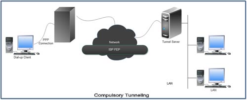
2. Compulsory Tunneling
A number of vendors that sell dial-up access servers have implemented the ability to create a tunnel on behalf of a dial up client. The computer or network device providing the tunnel for the diem computer is variously known as Ii Front EndProcessor (FEP) in PPTP, an L2TP Access Concentrator (LAC) in L2TP, or an security Gateway in IPSec. For the purposes of this white paper, the term FEP is used to describe this functionality regardless of the tunneling protocol. To carry out its function, the FEP must have the appropriate tunneling protocol installed and must be capable of establishing the tunnel when the client computer connects.
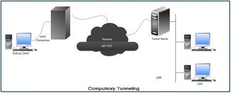
In the Internet-example, the client computer places a dial-up call to a tunneling-enabled NAS at the ISP. For example, a corporation may have contracted with an ISP to deploy a nationwide set of FEPs. These FEPs can establish tunnels across the Internet to a tunnel server connected to the corporation's private network, thus consolidating calls from geographically diverse locations into a single Internet connection at the corporate network.
This configuration is known as compulsory tunneling because, the client is compelled to use the tunnel created by the FEP. Once the initial connection is made, all network traffic to and from the client is automatically sent through the tunnel. With compulsory tunneling, the client computer makes a single PPP connection. When a client dials into the NAS, a tunnel is created and all traffic is automatically routed through the tunnel. An FEP can be configured to tunnel all dial-up clients to a specific tunnel server. The FEP could also tunnel individual clients, based on the user name or destination.
Unlike the separate tunnels created for each voluntary client, a tunnel between the FEP and the tunnel server can be shared by multiple dial-up clients. When a second client dials into the access server (FEP) to reach a destination for which a tunnel already exists, there is no need to create a new instance of the tunnel between the FEP and tunnel server. Instead, the data traffic for the new client is carried over the existing tunnel. Since there can be multiple clients in a single tunnel, the tunnel is not terminated until the last user of the tunnel disconnects.
This comment has been removed by the author.
ReplyDeleteNice Post!!! thanks for sharing this information with us.
ReplyDeleteAdvantages of Python